
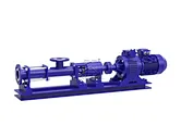
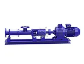
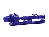


G Series Stepless Speed Regulating Progressive Cavity Pump
Inlet & Outlet Size: DN25–DN250
Flow Range: 0.15–150 m³/h
Pressure: 0.6–2.4 MPa
Motor Power: 0.75–55 kW
Speed: 10 r/min–960 r/min
Particle Size: 1.5–20 mm
Fiber Length: 25–150 mm
Voltage: 220V / 380V / 415V / 440V / 460V
What is G Series Stepless Speed Regulating Progressive Cavity Pump?
The G series stepless speed regulating progressive cavity pump (single screw pump) functions as a versatile positive displacement unit that balances smooth flow output with strong operational adaptability. Designed as an adjustable variable speed pump, it delivers high suction lift alongside low pressure pulsation, enabling simple transfer of standard free-flowing liquids as well as viscous, abrasive, or fiber-laden fluids. As one of the most reliable progressive cavity pumps for industrial processing, this single screw pc pump provides steady volumetric discharge across varying duty conditions.
Key Features
Smart Speed Control: Fitted with a mechanical stepless speed variator, this variable speed pump allows quick, effortless flow rate adjustments without requiring complex electrical control panels.
Versatile Media Handling: Outfitted with robust internal geometry, these progressive cavity pumps pump high-viscosity fluids, sludges, pastes, and media containing hard solids or fibrous materials.
Smooth & Stable Transfer: Featuring an internal-meshing rotor-stator design, this pc pump guarantees strong suction lift, uniform continuous delivery, and minimal pressure pulsation.
Cost-Effective Design: Delivers heavy-duty performance at a budget-friendly price point with straightforward maintenance, making this variable speed pump an ideal choice for economical installations.
Wide Applications
These positive displacement progressive cavity pumps suit diverse industrial environments, including wastewater treatment, petroleum processing, chemical production, food and beverage processing, brewing, papermaking, mining operations, textiles, and power generation plants. Deploying a regulated pc pump in these lines ensures smooth material movement and controlled fluid dosing.
Operating Principle
The progressive cavity pump (single screw pump) is a reliable positive displacement pump. Its core components are an eccentric screw (rotor) and a fixed rubber sleeve (stator). As the rotor turns, the media is continuously and smoothly transferred from the suction inlet to the discharge outlet.
Thanks to these features, the pump is ideal for the following applications:
-
Pumping high-viscosity media.
-
Handling fluids containing solid particles or fibers.
-
Requirements for continuous flow and stable pressure without pulsations.
-
Low-shear transfer that protects the structure of sensitive media.
-
Low noise operation.
Applications
As a versatile pump, the flow rate can be easily adjusted by changing the operation speed. The discharge pressure increases with the number of pump stages (0.6 MPa per stage). It is widely used in the following fields:
-
Environmental Protection: Industrial and domestic sewage, sludge water with solids or short fibers; ideal for oil-water separators and plate-and-frame filter presses.
-
Shipping & Marine: Bilge cleaning; transfer of oily water, oil sludge, and petroleum waste.
-
Petroleum Industry: Crude oil, oil-water mixtures, coalbed gas-water mixtures, and polymer injection.
-
Pharmaceuticals & Cosmetics: Various thick pastes, emulsions, and creams.
-
Food & Canning: Thick starch, cooking oil, honey, syrups, fruit pulp, cream, minced fish, and food processing waste.
-
Brewing & Distilling: Fermented mash, distillers' grains, grain residues, thick sauces, and viscous liquids with solid chunks.
-
Construction: Spraying and transferring cement mortar, lime slurry, coatings, and other pastes.
-
Mining: Pumping underground water and muddy water with solid particles from mines to the surface.
-
Chemical Industry: Various suspensions, greases, colloidal slurries, and adhesives.
-
Printing & Papermaking: High-viscosity inks, PVC paste for wallpaper, and various paper pulps or short-fiber slurries.
-
Boilers & Power Plants: Coal-water slurry (CWM) transfer.
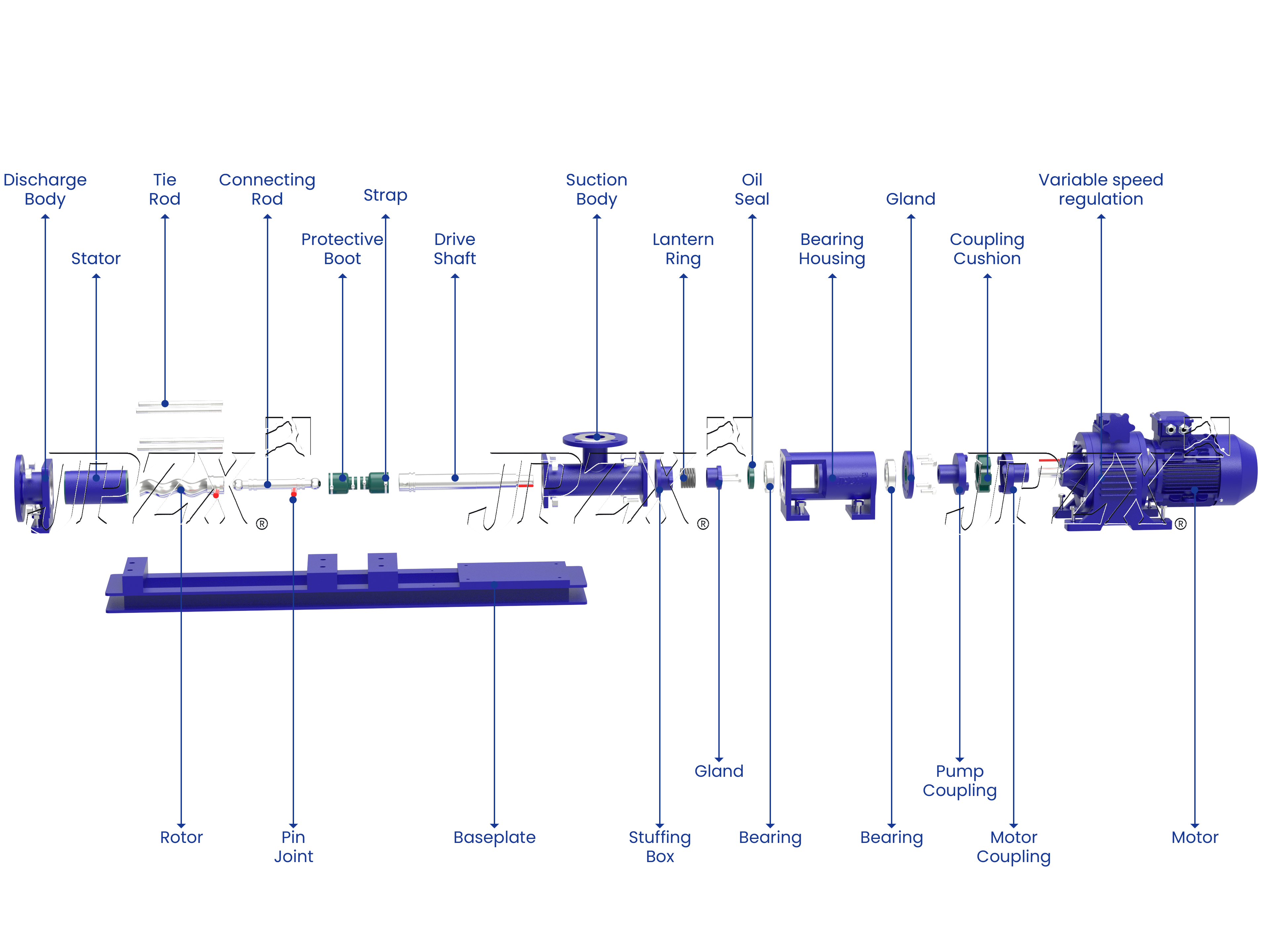
Table 1: Performance Parameters at Fixed Speed
|
Model |
Flow Rate (m³/h) |
Pressure (MPa) |
Max. Allowable Speed (rpm) |
Motor Power (kW) |
NPSHr (m) |
Inlet Flange Dia. (mm) |
Outlet Flange Dia. (mm) |
Max. Particle Dia. (mm) |
Max. Fiber Length (mm) |
|
G20-1 |
0.8 |
0.6 |
960 |
0.75 |
4 |
25 |
25 |
1.5 |
25 |
|
G20-2 |
0.8 |
1.2 |
960 |
1.1 |
4 |
25 |
25 |
1.5 |
25 |
|
G25-1 |
2 |
0.6 |
960 |
1.5 |
4 |
32 |
25 |
2 |
30 |
|
G25-2 |
2 |
1.2 |
960 |
2.2 |
4 |
32 |
25 |
2 |
30 |
|
G30-1 |
5 |
0.6 |
960 |
2.2 |
4 |
50 |
40 |
2.5 |
35 |
|
G30-2 |
5 |
1.2 |
960 |
3 |
4 |
50 |
40 |
2.5 |
35 |
|
G35-1 |
8 |
0.6 |
960 |
3 |
4 |
65 |
50 |
3 |
40 |
|
G35-2 |
8 |
1.2 |
960 |
4 |
4 |
65 |
50 |
3 |
40 |
|
G40-1 |
12 |
0.6 |
960 |
4 |
4 |
80 |
65 |
3.8 |
45 |
|
G40-2 |
12 |
1.2 |
960 |
5.5 |
4 |
80 |
65 |
3.8 |
45 |
|
G50-1 |
20 |
0.6 |
960 |
5.5 |
4.5 |
100 |
80 |
5 |
50 |
|
G50-2 |
20 |
1.2 |
960 |
7.5 |
4.5 |
100 |
80 |
5 |
50 |
|
G60-1 |
30 |
0.6 |
960 |
11 |
5 |
125 |
100 |
6 |
60 |
|
G60-2 |
30 |
1.2 |
960 |
15 |
5 |
125 |
100 |
6 |
60 |
|
G70-1 |
38 |
0.6 |
720 |
11 |
5 |
150 |
125 |
8 |
70 |
|
G70-2 |
38 |
1.2 |
720 |
15 |
5 |
150 |
125 |
8 |
70 |
|
G85-1 |
60 |
0.6 |
720 |
18.5 |
5 |
150 |
150 |
10 |
80 |
|
G85-2 |
50 |
1.2 |
600 |
22 |
5 |
150 |
150 |
10 |
80 |
|
G105-1 |
80 |
0.6 |
380 |
22 |
5 |
200 |
200 |
15 |
110 |
|
G105-2 |
80 |
1.2 |
380 |
37 |
5 |
200 |
200 |
15 |
110 |
|
G135-1 |
150 |
0.6 |
380 |
37 |
5 |
250 |
250 |
20 |
150 |
|
G135-2 |
150 |
1.2 |
380 |
55 |
5 |
250 |
250 |
20 |
150 |
Table2: Single-Stage Screw Pump with Variable Speed Gearbox / Motor Drive
|
Model |
Gear Reducer Drive (0.6MPa Working Pressure) |
Variable Speed Motor Drive (Adjustable) |
|||||||
|
Speed (rpm) |
Flow Rate (m³/h) |
Motor Spec. (kW) |
Speed (rpm) |
Flow Rate (m³/h) |
Motor Spec. (kW) |
Speed (rpm) |
Flow Rate (m³/h) |
Motor Power (kW) |
|
|
G20-1 |
960 |
0.8 |
0.75-6P |
480 |
0.4 |
0.55-4P / Gearbox |
200~1000 |
0.16~0.8 |
0.75 |
|
720 |
0.8 |
0.75-8P |
320 |
0.27 |
0.55-4P / Gearbox |
||||
|
640 |
0.54 |
0.75-4P / Gearbox |
200 |
0.16 |
0.55-4P / Gearbox |
||||
|
G25-1 |
960 |
2 |
1.5-6P |
480 |
1 |
1.1-4P / Gearbox |
200~1000 |
0.41~2 |
1.5 |
|
720 |
1.5 |
1.5-8P |
320 |
0.66 |
0.75-4P / Gearbox |
||||
|
640 |
1.3 |
1.5-4P / Gearbox |
200 |
0.41 |
0.75-4P / Gearbox |
||||
|
G30-1 |
960 |
5 |
2.2-6P |
480 |
2.5 |
1.5-4P / Gearbox |
200~1000 |
1.04~5 |
2.2 |
|
720 |
3.74 |
2.2-8P |
320 |
1.66 |
1.1-4P / Gearbox |
||||
|
640 |
3.33 |
2.2-4P / Gearbox |
200 |
1.04 |
1.1-4P / Gearbox |
||||
|
G35-1 |
960 |
8 |
3-6P |
480 |
4 |
2.2-4P / Gearbox |
200~1000 |
1.66~8 |
3 |
|
720 |
6 |
3-8P |
320 |
2.66 |
1.5-4P / Gearbox |
||||
|
640 |
5.33 |
3-4P / Gearbox |
200 |
1.66 |
1.5-4P / Gearbox |
||||
|
G40-1 |
960 |
12 |
4-6P |
480 |
6 |
3-4P / Gearbox |
200~1000 |
2.5~12 |
4 |
|
720 |
9 |
4-8P |
320 |
4 |
2.2-4P / Gearbox |
||||
|
640 |
8 |
4-4P / Gearbox |
200 |
2.5 |
2.2-4P / Gearbox |
||||
|
G50-1 |
960 |
20 |
5.5-6P |
480 |
10 |
4-4P / Gearbox |
200~1000 |
4.16~20 |
5.5 |
|
720 |
15 |
5.5-8P |
320 |
6.66 |
3-4P / Gearbox |
||||
|
640 |
13.3 |
5.5-4P / Gearbox |
200 |
4.16 |
3-4P / Gearbox |
||||
|
G60-1 |
960 |
30 |
11-6P |
480 |
15 |
7.5-4P / Gearbox |
200~1000 |
6.25~30 |
11 |
|
720 |
22.5 |
11-8P |
320 |
10 |
5.5-4P / Gearbox |
||||
|
640 |
20 |
11-4P / Gearbox |
200 |
6.25 |
5.5-4P / Gearbox |
||||
|
G70-1 |
720 |
38 |
11-8P |
400 |
21.11 |
11-4P / Gearbox |
200~720 |
12.5~38 |
11 |
|
600 |
31.2 |
11-4P / Gearbox |
300 |
15.83 |
7.5-4P / Gearbox |
||||
|
500 |
26.38 |
11-4P / Gearbox |
200 |
10.55 |
7.5-4P / Gearbox |
||||
|
G85-1 |
720 |
60 |
18.5-8P |
400 |
33.33 |
15-4P / Gearbox |
200~720 |
16.66~60 |
18.5 |
|
600 |
50 |
18.5-4P / Gearbox |
300 |
25 |
11-4P / Gearbox |
||||
|
500 |
41.66 |
15-4P / Gearbox |
200 |
16.66 |
11-4P / Gearbox |
||||
|
G105-1 |
380 |
80 |
22-4P / Gearbox |
200 |
42.1 |
18.5-4P / Gearbox |
32~90 |
3~50 |
22 |
|
320 |
67.36 |
22-4P / Gearbox |
160 |
33.68 |
18.5-4P / Gearbox |
||||
|
260 |
54.73 |
22-4P / Gearbox |
100 |
21.05 |
15-4P / Gearbox |
||||
|
G135-1 |
380 |
120 |
37-4P / Gearbox |
200 |
63.15 |
30-4P / Gearbox |
18~180 |
3~56 |
45 |
|
320 |
101 |
37-4P / Gearbox |
160 |
50.52 |
30-4P / Gearbox |
||||
|
260 |
82 |
37-4P / Gearbox |
100 |
31.57 |
22-4P / Gearbox |
||||
Table3:Performance Parameters (Pressure: 1.2 MPa / Head: 120 m)
|
Model |
Gear Reducer Drive (1.2MPa Working Pressure / 120m Head) |
Variable Speed Motor Drive (Adjustable) |
|||||||
|
Speed (rpm) |
Flow Rate (m³/h) |
Motor Spec. (kW) |
Speed (rpm) |
Flow Rate (m³/h) |
Motor Spec. (kW) |
Speed (rpm) |
Flow Rate (m³/h) |
Motor Power (kW) |
|
|
G20-2 |
960 |
0.8 |
1.1-6P |
480 |
0.4 |
0.75-4P / Gearbox |
200~1000 |
0.16~0.8 |
1.1 |
|
720 |
0.8 |
1.1-8P |
320 |
0.27 |
0.55-4P / Gearbox |
||||
|
640 |
0.54 |
1.1-4P / Gearbox |
200 |
0.16 |
0.55-4P / Gearbox |
||||
|
G25-2 |
960 |
2 |
2.2-6P |
480 |
1 |
1.5-4P / Gearbox |
200~1000 |
0.41~2 |
2.2 |
|
720 |
1.5 |
2.2-8P |
320 |
0.66 |
1.1-4P / Gearbox |
||||
|
640 |
1.3 |
2.2-4P / Gearbox |
200 |
0.41 |
1.1-4P / Gearbox |
||||
|
G30-2 |
960 |
5 |
3-6P |
480 |
2.5 |
2.2-4P / Gearbox |
200~1000 |
1.04~5 |
3 |
|
720 |
3.74 |
3-8P |
320 |
1.66 |
1.5-4P / Gearbox |
||||
|
640 |
3.33 |
3-4P / Gearbox |
200 |
1.04 |
1.5-4P / Gearbox |
||||
|
G35-2 |
960 |
8 |
4-6P |
480 |
4 |
3-4P / Gearbox |
200~1000 |
1.66~8 |
4 |
|
720 |
6 |
4-8P |
320 |
2.66 |
2.2-4P / Gearbox |
||||
|
640 |
5.33 |
4-4P / Gearbox |
200 |
1.66 |
2.2-4P / Gearbox |
||||
|
G40-2 |
960 |
12 |
5.5-6P |
480 |
6 |
4-4P / Gearbox |
200~1000 |
2.5~12 |
5.5 |
|
720 |
9 |
5.5-8P |
320 |
4 |
3-4P / Gearbox |
||||
|
640 |
8 |
5.5-4P / Gearbox |
200 |
2.5 |
3-4P / Gearbox |
||||
|
G50-2 |
960 |
20 |
7.5-6P |
480 |
10 |
5.5-4P / Gearbox |
200~1000 |
4.16~20 |
7.5 |
|
720 |
15 |
7.5-8P |
320 |
6.66 |
4-4P / Gearbox |
||||
|
640 |
13.3 |
7.5-4P / Gearbox |
200 |
4.16 |
4-4P / Gearbox |
||||
|
G60-2 |
720 |
30 |
11-8P |
400 |
16.66 |
7.5-4P / Gearbox |
63~630 |
1~20 |
15 |
|
600 |
25 |
11-4P / Gearbox |
300 |
12.5 |
5.5-4P / Gearbox |
||||
|
500 |
20.83 |
11-4P / Gearbox |
200 |
8.33 |
5.5-4P / Gearbox |
||||
|
G70-2 |
720 |
38 |
15-8P |
400 |
21.11 |
11-4P / Gearbox |
56~560 |
1~22 |
15 |
|
600 |
31.66 |
15-4P / Gearbox |
300 |
15.83 |
11-4P / Gearbox |
||||
|
500 |
26.38 |
15-4P / Gearbox |
200 |
10.55 |
7.5-4P / Gearbox |
||||
|
G85-2 |
600 |
50 |
22-4P / Gearbox |
300 |
25 |
15-4P / Gearbox |
37~370 |
2~24 |
22 |
|
500 |
41.66 |
22-4P / Gearbox |
200 |
16.66 |
11-4P / Gearbox |
||||
|
400 |
33.33 |
18.5-4P / Gearbox |
100 |
8.33 |
11-4P / Gearbox |
||||
|
G105-2 |
380 |
80 |
37-4P / Gearbox |
200 |
42.1 |
22-4P / Gearbox |
29~290 |
3~50 |
37 |
|
320 |
67.36 |
37-4P / Gearbox |
160 |
33.68 |
22-4P / Gearbox |
||||
|
260 |
54.73 |
37-4P / Gearbox |
100 |
21.05 |
22-4P / Gearbox |
||||
Table4:Performance Parameters for Single & Two-Stage Screw Pumps
|
Pump Model |
Flow Rate (m³/h) |
Working Pressure (MPa) |
Speed (rpm) |
Gear Reducer Matched Adjustable Motor Model (kW) |
|
G30-2 |
0.15~1.56 |
1.2 |
30~300 |
YCT160/4A-2.2 |
|
G35-2 |
0.25~2.5 |
1.2 |
30~300 |
YCT160/4A-2.2 |
|
G40-2 |
0.37~3.5 |
1.2 |
30~280 |
YCT160/4A-3 |
|
G50-1 |
0.58~5.83 |
0.6 |
28~280 |
YCT180/4A-4 |
|
G50-2 |
0.52~5.2 |
1.2 |
25~250 |
YCT200/4A-5.5 |
|
G60-1 |
0.78~7.81 |
0.6 |
25~250 |
YCT200/4A-5.5 |
|
G60-2 |
1.04~10.41 |
1.2 |
25~250 |
YCT200/4B-7.5 |
|
G70-1 |
1.31~11.61 |
0.6 |
25~220 |
YCT200/4B-7.5 |
|
G85-1 |
1.5~15 |
0.6 |
18~180 |
YCT225/4A-11 |
|
G105-1 |
2.94~29.47 |
0.6 |
14~140 |
YCT225/4B-15 |
|
G135-1 |
3.15~31.57 |
0.6 |
10~100 |
YCT250/4B-22 |
Q1: What is the main benefit of the stepless speed regulation function on this screw pump?
It allows operators to manually adjust the motor speed on the spot to control the liquid flow rate precisely. This means you don't need to change system piping or buy separate frequency converters (VFDs) when your production line requires different dosing speeds or handles liquids of varying thickness.
Q2: Why is adjustable speed especially important when pumping viscous or easily damaged materials?
Thicker liquids require lower speeds to prevent cavitations, while shear-sensitive materials (like food paste or polymers) can degrade if pumped too fast. By slowing down the pump speed, you protect material quality, prevent pipeline blockage, and extend the lifespan of the internal rubber sleeve.
Q3: What drives or speed control options are available for automated plant setups?
Manual Mechanical Stepless Reducer: Handwheel-operated speed control, cost-effective for static field operations.
VFD (Variable Frequency Drive) Motor: Allows remote, automated speed and flow control via PLC system signals.
Explosion-Proof Variable Speed Motor: Required for hazardous chemical areas where speed regulation is needed in flammable environments.
Q4: How does adjusting speed affect the output pressure of the pump?
No. The output pressure is mainly determined by the resistance of your pipeline and the pump's rotor-stator stage design, not the speed. Changing the speed only increases or decreases the flow volume, while the pump maintains stable, high discharge pressure even at low RPM.
Recommend Products


CONTACT JIUJIANG



Telephone
+86 18167392360
Mailbox
Address
No.16 Linwu Road, Oubei Street, Yongjia, Wenzhou, Zhejiang, China